Overview
The trigger interface
- Login to MiOS EZlogic
- Click ‘Meshbot Automation’
- Click ‘Create New Meshbot’
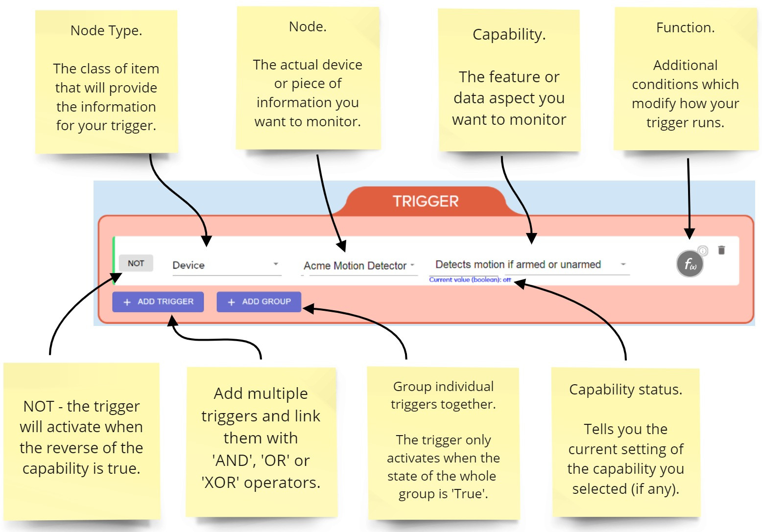
Node Types
The node type is the class of device or type of data that will provide the source information for your trigger. Your choice here determines what drop-down menus and interfaces you can configure in the rest of the trigger. You can choose one of the following node types:- Device – The meshbot will run the action when a device changes status. For example, if the temperature changes, or a door opens, or motion is detected. See the Device page if you need more help with this.Some devices have capabilities that let you set a custom value:
- Expression – An expression is a piece of code which is capable of housing various values. You can reference these values in a meshbot and use it to trigger an action. See the Expressions page if you need more help with this.
- Value – Enter a specific integer or state that you want to use to activate the trigger. Values may be boolean (true/false) or an integer (a number, scale or percentage) depending on the requirements of the device capability.
- Variable – A variable is a user-created item used to house a specific piece of data. For example, you could use a variable to store the ‘on/off’ state of a switch, or the temperature from your thermostat, or some data from an external resource such as a website. See the Variables page for more information.
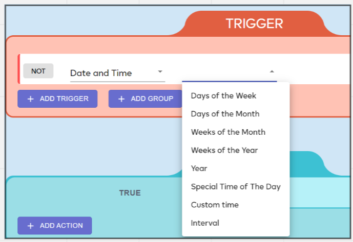
- Date and Time – The meshbot will activate according to a schedule of your choice, be that hourly, daily, weekly, monthly, at certain intervals, between specific times, or at sunrise/sunset. See the Date and Time page if you need more help with this.
- Meshbot – The meshbot will run based on the outcome of the actions of another meshbot. See the Meshbot page if you want more help with this.
- House Mode – A house mode is a collection of device settings that let you set the status of a range of devices with a single click. Each mode is configured with settings to arm devices and take actions in accordance with typical user needs during this time. For example, ‘Night Mode’ will arm all of your sensors and alarms and lock all of your doors. See the House Modes page for more information.
- Controller – Use the status of your smart-home hub to trigger actions and scenes. You can trigger actions based on the controller’s battery level, charging status or whether it currently has a connection to MiOS cloud services. See the controller help page to learn more about this type of node.
- Expression – Expressions let you retrieve the current status or setting of a device and use that value as the condition of your trigger. For example, if the current temperature of your thermostat is X degrees Fahrenheit then turn the trigger true and run an action. See the Expressions page for more help with this node type.
- Local Variable – Use the current value of an existing variable as the condition of your trigger. You can create triggers which activate when a variable achieves a specific value (e.g., when variable ‘X’ >= ‘27’ or when variable ‘Y’ = ‘False’). You can also use a comparison of one variable with another variable to trigger your action (e.g. if ‘Current Temperature Variable’ >= ‘Switch on the AC Variable’). See the variables help page for more assistance with this node type.
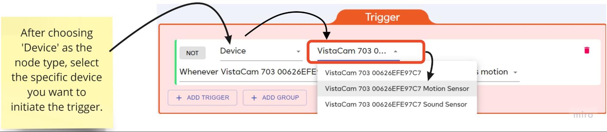
Node
The node is the specific device or data type that you want to monitor in the trigger. It is the ‘subcategory’ of the node type you selected in the first menu. The items you see here depend on which node type you selected earlier.
For example, if you selected ‘Device’ as your type then the node menu lets you choose from a list of every device in your network:
Capability
The device feature that you want to monitor for change in order to activate the trigger. ‘Capability’ is unique to the device node type. For example, a motion detector may have the following capabilities: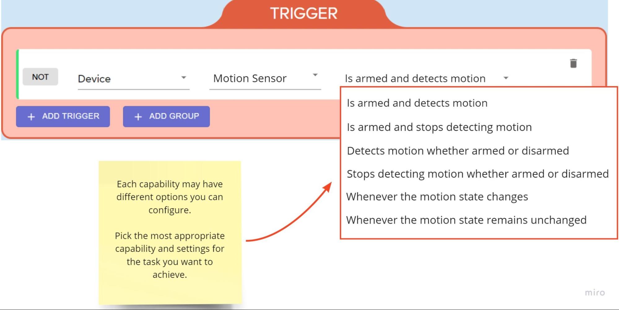
Each capability may present you with different options that you can set. Experiment to find the best capability and settings for the task you have in mind.
The comparator field lets you set the relationship between the current value of a device capability and a specific value you want to use as the condition of your trigger. For example, turn on your air conditioning IF the thermostat records a temperature GREATER THAN than X.
You will only see this field for device capabilities that can have a range of different values over time. For example, power level, temperature, volume, fan speed, battery level etc.
The following image shows a simple trigger that will go true if the battery level of a thermostat is between 0% and 20%. You could then create actions to put the thermostat in economy mode and send out a notification when the trigger becomes true:
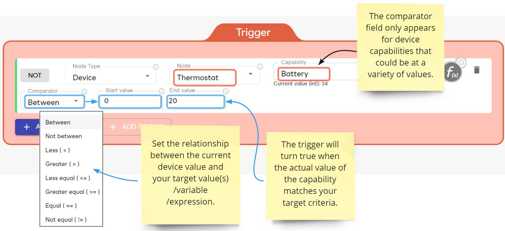
‘Between’ and ‘Not Between’ require you to enter upper and lower values. All other comparators let you choose a value, expression or variable as your criteria:
Value – Simply enter the value that the device must achieve in order to turn your trigger true. The ‘Between’ and ‘Not Between’ comparators let you specify upper and lower values.
Expression – Use the current value of an expression as your target condition. This will, for example, let you use a comparison of the current values of two different devices as your trigger condition. See the Expressions page if you want to learn more about expressions.
Variable – Use the value of one of your variables as your target condition. You can create variables of various different types in the ‘Variables’ section of EZLogic. You can also use the ‘Save Output’ feature of a HTTP/NuCAL meshbot action to fetch and store dynamic values to a variable. See the Variables page for more information.
Functions
Functions are additional conditions that you can add to a trigger to modify how it behaves.
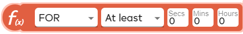
FOR – The trigger only activates if your condition remains true for the length of time you specify. For example, a door must remain unlocked for 3 minutes before sending out an alert notification. See the FOR page if you want more help with this.
REPEAT – The trigger only activates if your condition is true multiple times during a set time-period. For example, a security camera only starts recording if a motion sensor is tripped 3 times in 30 seconds. See the REPEAT page if you want more help with this.
FOLLOW – Temporarily keep the state of a trigger at ‘true’, even when its conditions have become false. For example, to keep a hallway light switched on for 3 minutes when a motion sensor detects movement, even if the person stops moving. See the FOLLOW page if you want more help with this.
PULSE – Lets you run actions which repeat at an interval of your choice based on whether or not the trigger is true. For example, you want Alexa to issue voice notifications every 3 minutes if your front door is left open. See the PULSE page if you want more help with this.
LATCH – Locks a trigger at true indefinitely once its condition becomes true. It will remain true until the trigger is reset. For example, you have a trigger which activates when a dynamic variable hits a certain value, but you don’t want the trigger to become false (and stop the action) if the variable changes. See the LATCH page if you want more help with this.
Trigger Groups
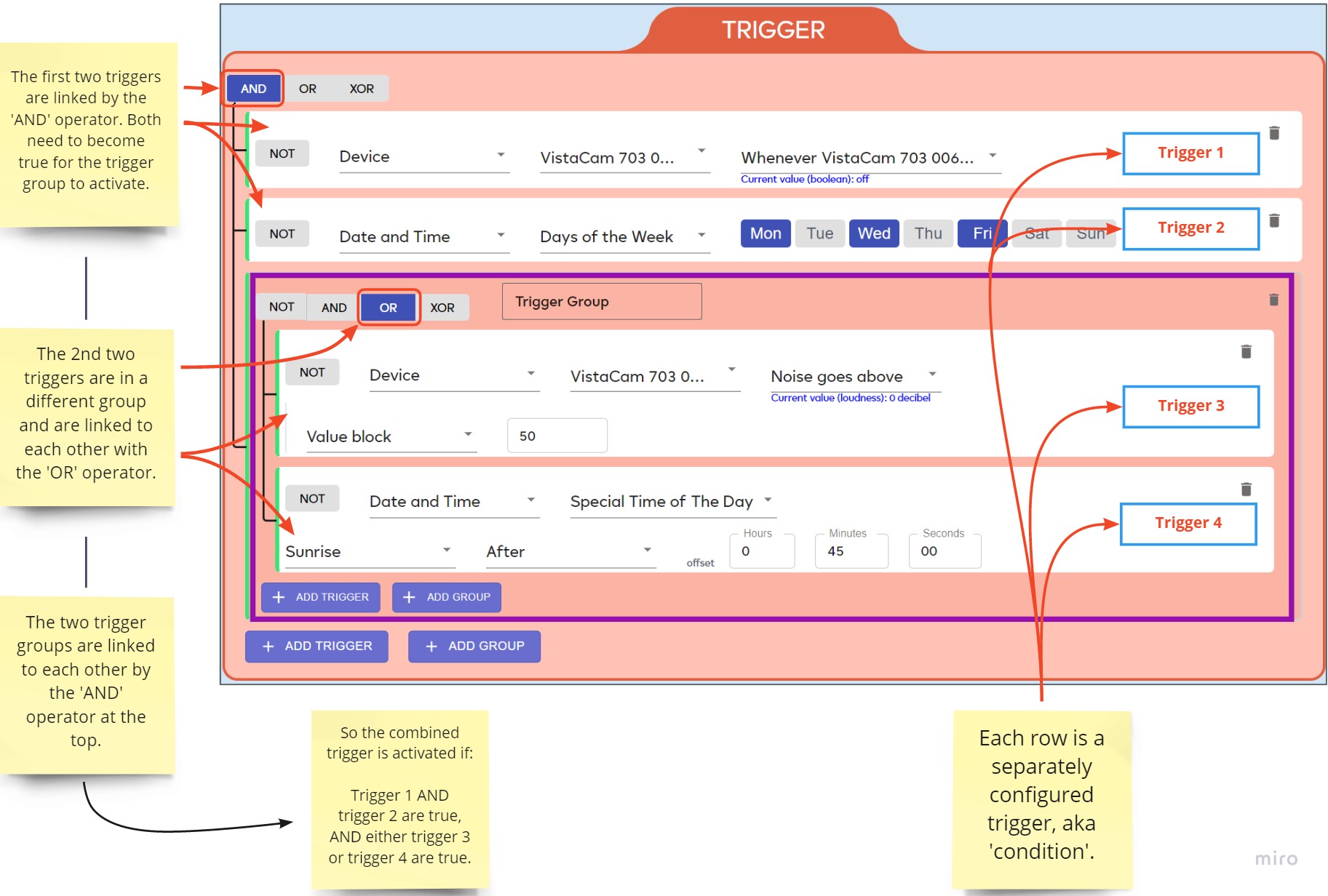
Trigger groups allow you to better organize, visualize and logically connect your trigger conditions. This lets you create more complex triggers which target very specific situations.
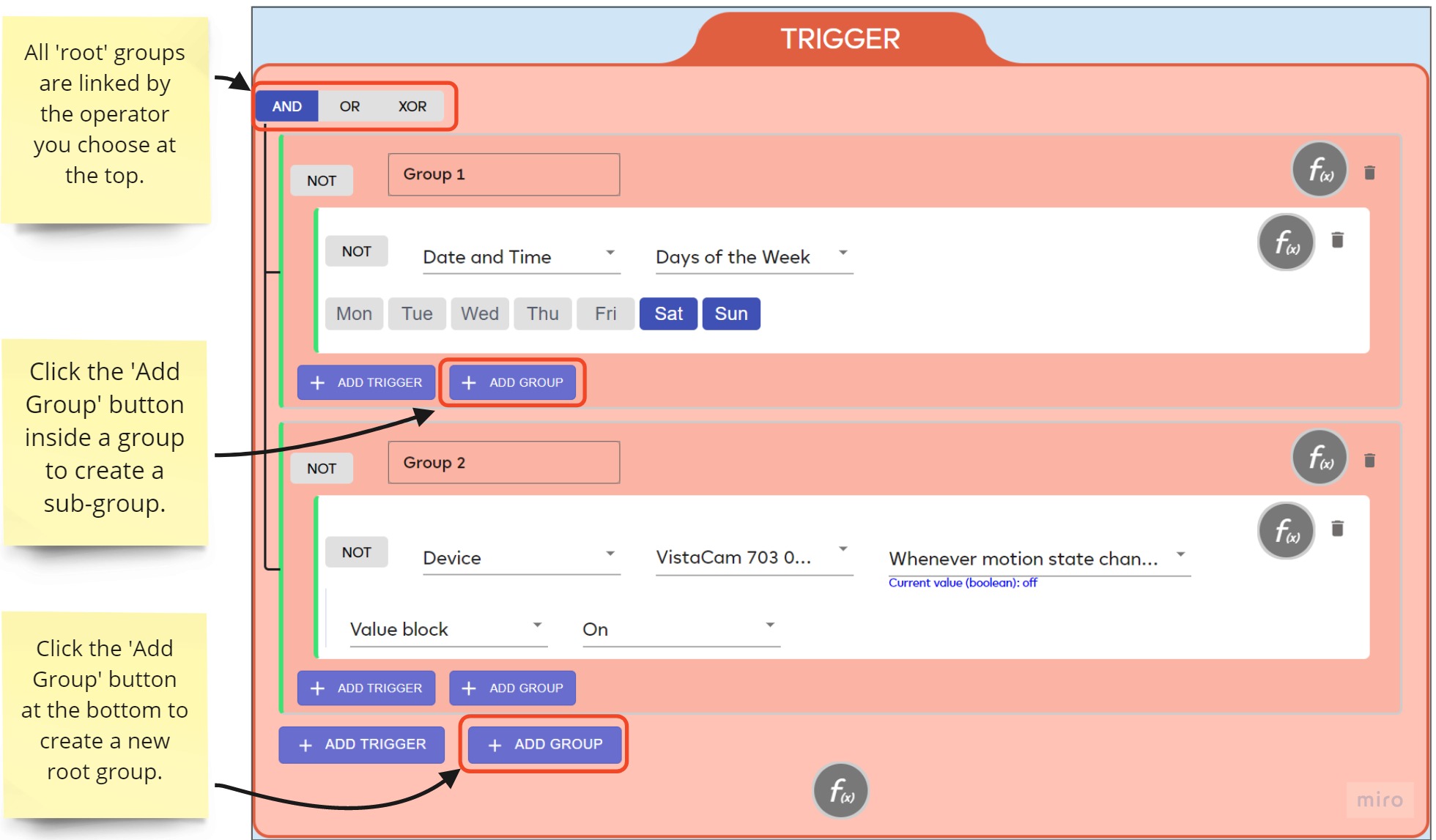
- The relationship between all groups in a set is determined by the uppermost operator group in the trigger set.
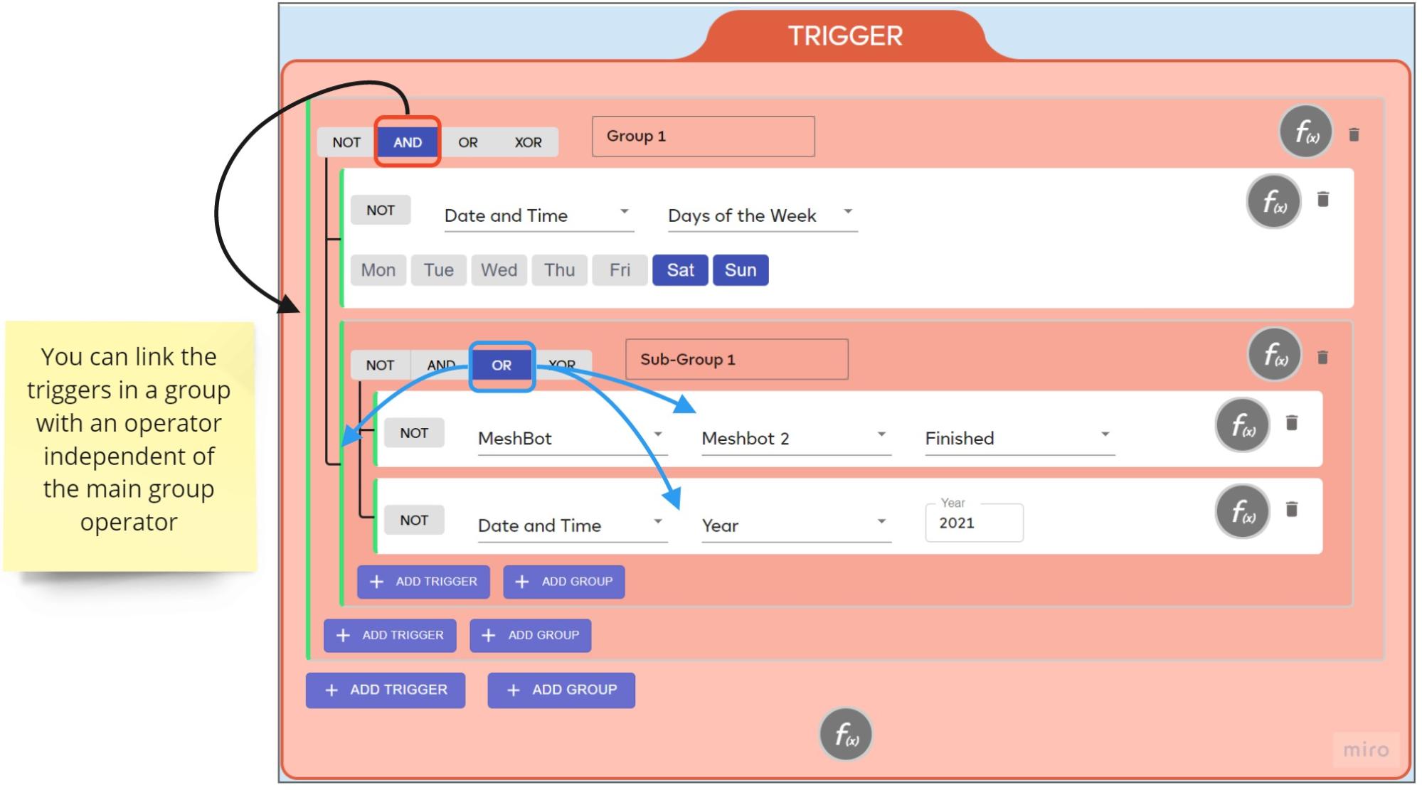
- You can create a new group by clicking the ‘Add Group’ button at the bottom of the trigger interface. You can then link the triggers within the group with the operator of your choice.
- You can create nested groups by clicking the ‘Add Group’ button inside the group itself. You can then link the sub-groups with the operator of your choice, and the triggers within the sub-groups with yet another operator.
- NOT is a complement to, rather than a substitute for, operators like ‘AND’, ‘OR’ or ‘XOR’. You can apply NOT to individual triggers and groups, but can’t use it to establish the relationship between triggers and groups.
Why use a trigger group?
- Functionality. You can only connect individual triggers with a single operator – either ‘AND’, ‘OR’ or ‘XOR’. While this is fine for a simple or two-trigger scenario, you can run into problems if you want a more nuanced trigger set with three or more conditions. Groups let you connect multiple triggers together with various operators as required by your task.
- Organization. In complex scenarios, groups let you consolidate the many triggers for an action in a single place. Without them, you’d have to create separate meshbots with different trigger-actions to accomplish the same overall task.
To illustrate, let’s look at an example task:
Requirement — Play music in the living room between 8 PM and 11 PM on weekdays, between 7 PM and 11.30 PM on weekends, and between 7 AM and 9 AM in the morning every day UNLESS the television is switched-on or the house-mode is ‘Vacant Mode’.
When split into conditions, the example above has eight different triggers to consider. Without groups, you’d only have one operator to link them all:
- Weekdays
- 8 PM — 11 PM
- Weekend
- 7 PM — 11.30 PM
- Every Day
- 7 AM — 9 AM
- TV off
- Vacant Mode off
- You can’t ‘AND’ them all together because many items are mutually exclusive. For example, it is never both a weekday and a weekend at the same time. Similarly, you couldn’t use ‘OR’ because the ‘everyday’ condition would overrule everything else and make the music play non-stop. XOR is a non-starter as it is literally impossible for only one of the date/time conditions to be true at any given time.
- Your only other option is to set up and run three different meshbots, each with the same action of ‘Play music in the living room’:
- Weekdays AND 8 pm – 11 pm AND TV off AND vacant mode off.
- Weekend AND 7 pm – 11.30 pm AND TV off AND vacant mode off.
- Every Day AND 7 am – 9 am AND TV off AND vacant mode off.
| T R I G G E R |
OR | Group 1 - Weekdays | |
| AND | Mon, Tue, Wed, Thur, Fri | ||
| 8 PM — 11 PM | |||
| Television Off | |||
| Vacant Mode Off | |||
| Group 2 — Weekends | |||
| AND | Sat, Sun | ||
| 7 PM — 11.30 PM | |||
| Television Off | |||
| Vacant Mode Off | |||
| Group 3 — Every Morning | |||
| AND | Mon, Tue, Wed, Thur, Fri, Sat, Sun | ||
| 7 AM — 9 AM | |||
| Television Off | |||
| Vacant Mode Off | |||
| Action | Music Center | Turn On | |
And here’s how the same meshbot would look in the EZlogic interface:
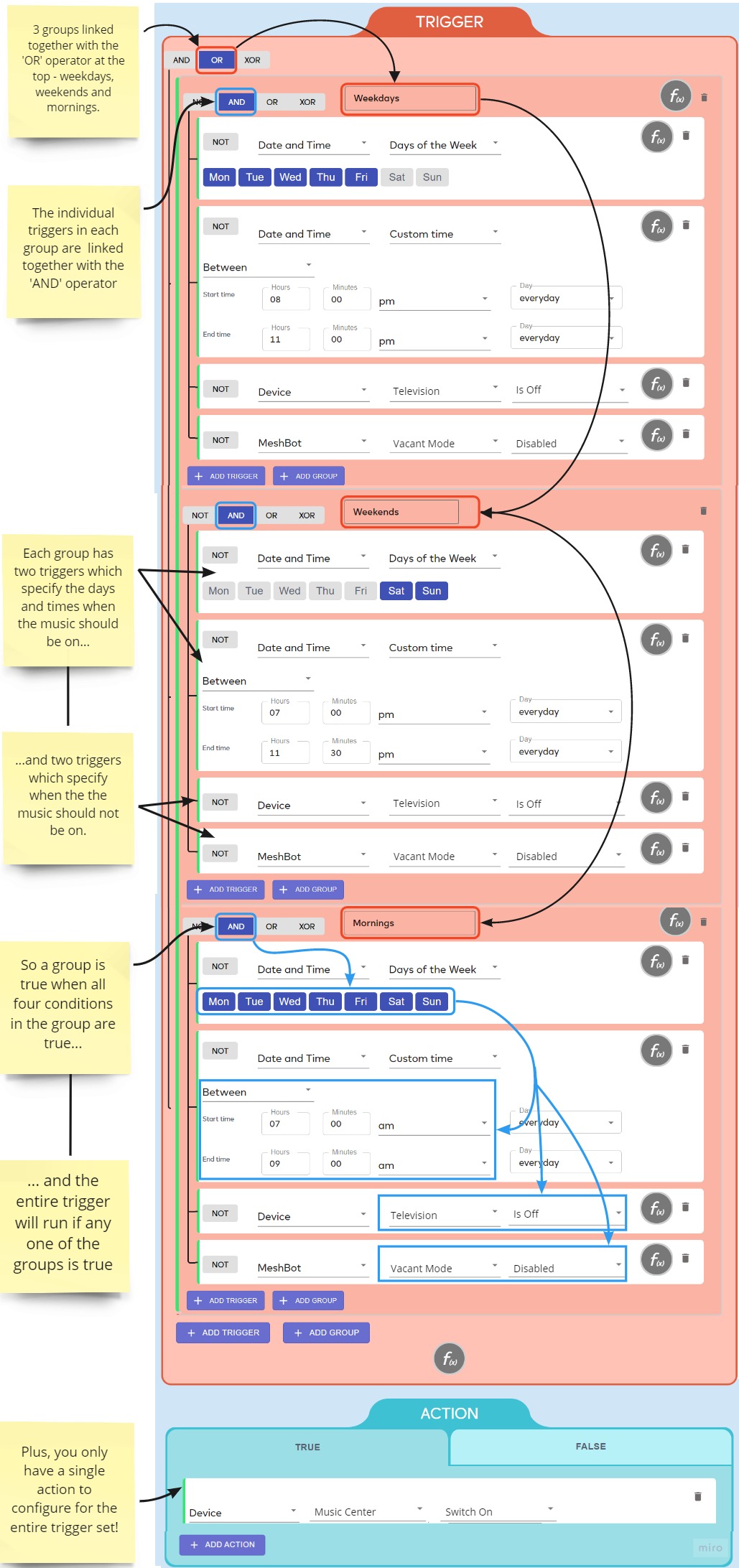
Can you think of a better way using fewer conditions? A fancier rule set using nested groups and XOR conditions? Go for it – experiment, test and find out what works best for you. The key take-away is that reducing the number of meshbots you have running makes it far easier to manage and update them as your task list grows. It’s also a great way to learn rule-logic and become better at using the system.
Operators / logic gates and NOT
You can use the following items to connect or invert triggers, actions and/or groups in a meshbot:
NOT
This means ‘if the reverse of the named condition is true then proceed’. If we clicked ‘NOT’ in the example below then it would trigger the action when the sensor did not detect motion: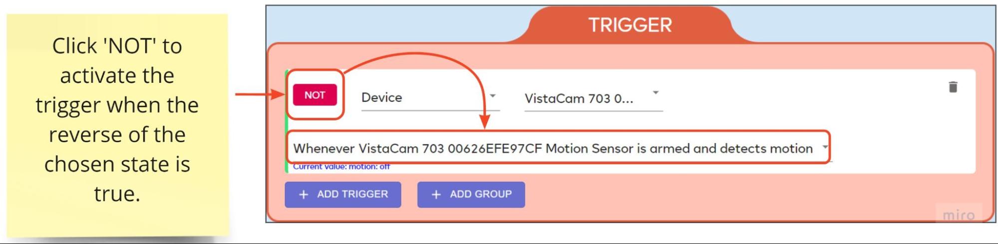
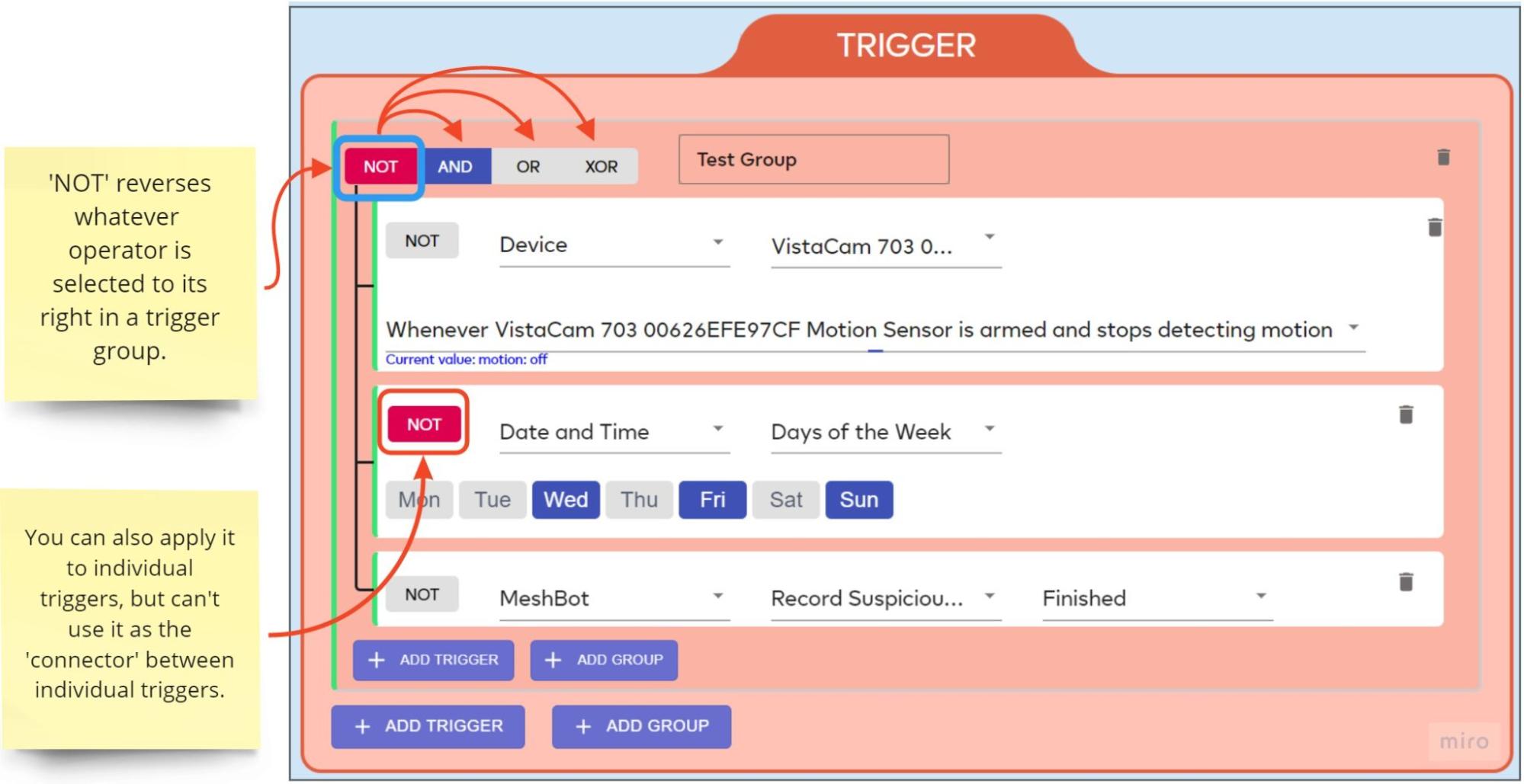
Similarly, if we chose ‘Wednesday’ as the trigger day, then clicked ‘NOT’, it would execute the action on all days except Wednesday.
You can apply NOT to individual triggers and trigger groups, but cannot use it to establish the connection between individual triggers.
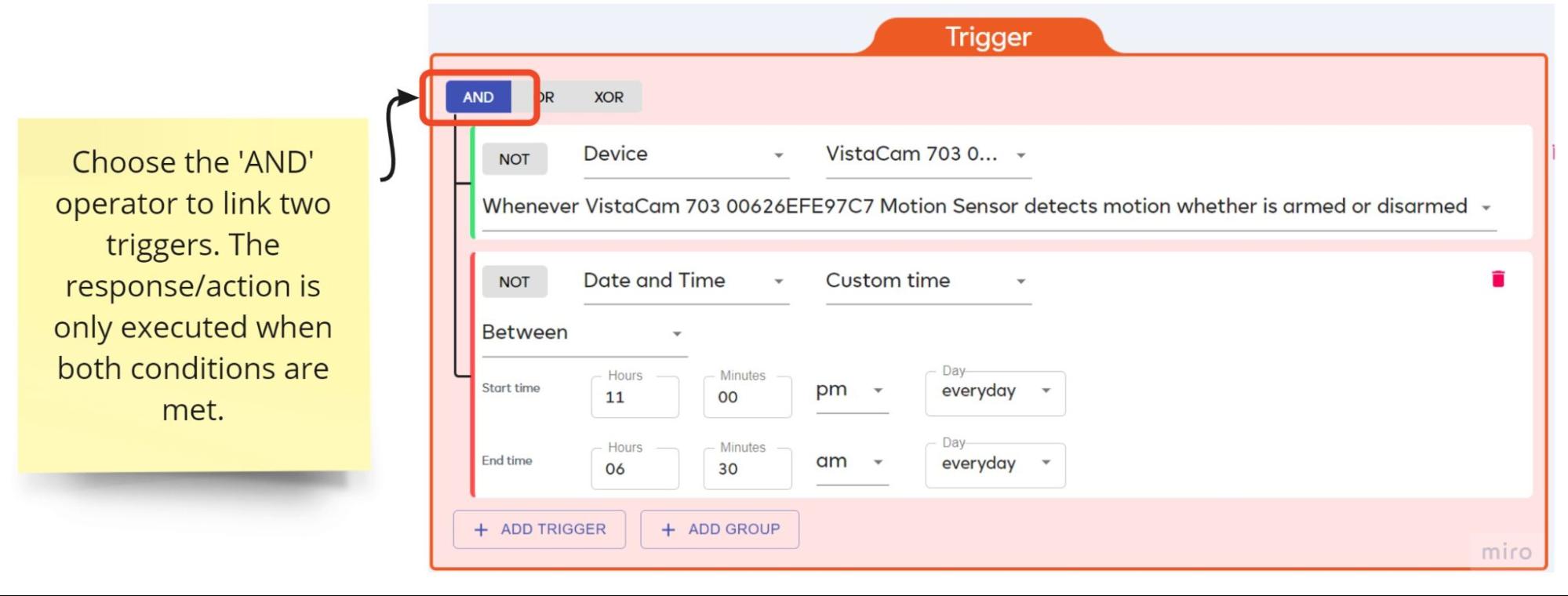
AND
Executes the action only when the state of every linked trigger is true. For example, ‘When the motion sensor detects movement’ AND ‘The time is between 11 PM and 6.30 AM’:
Here’s a table to illustrate how the states of 3 triggers linked by AND contribute to the state of the trigger group:
| Trigger 1 | Trigger 2 | Trigger 3 | Trigger Group |
|---|---|---|---|
| False | False | False | False |
| False | False | True | False |
| False | True | False | False |
| False | True | True | False |
| True | False | False | False |
| True | False | True | False |
| True | True | False | False |
| True | True | True | True |
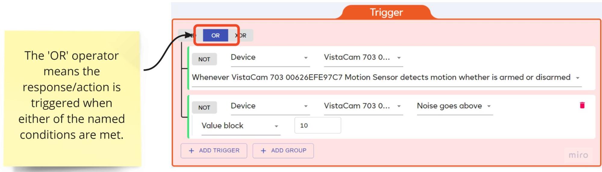
OR
Executes the action when any or all of the conditions in the trigger group are true. For example, ‘When the motion sensor detects movement’ OR ‘The ambient noise goes above a certain level’ (or both happen):
If one condition is true then the trigger group becomes true. If another condition subsequently becomes true, then the group remains true. In case there’s some confusion, please note that the second ‘true’ doesn’t somehow ‘double’ the actions by firing another instance of the action. The group just maintains its status of ‘true’.
Here’s a table to illustrate how the states of 3 triggers linked by OR contribute to the state of the trigger group:
| Trigger 1 | Trigger 2 | Trigger 3 | Trigger Group |
|---|---|---|---|
| False | False | False | False |
| False | False | True | True |
| False | True | False | True |
| False | True | True | True |
| True | False | False | True |
| True | False | True | True |
| True | True | False | True |
| True | True | True | True |
In other words, the group is only false when all triggers are false.
XOR
Executes the action only if exactly one of the conditions is true.
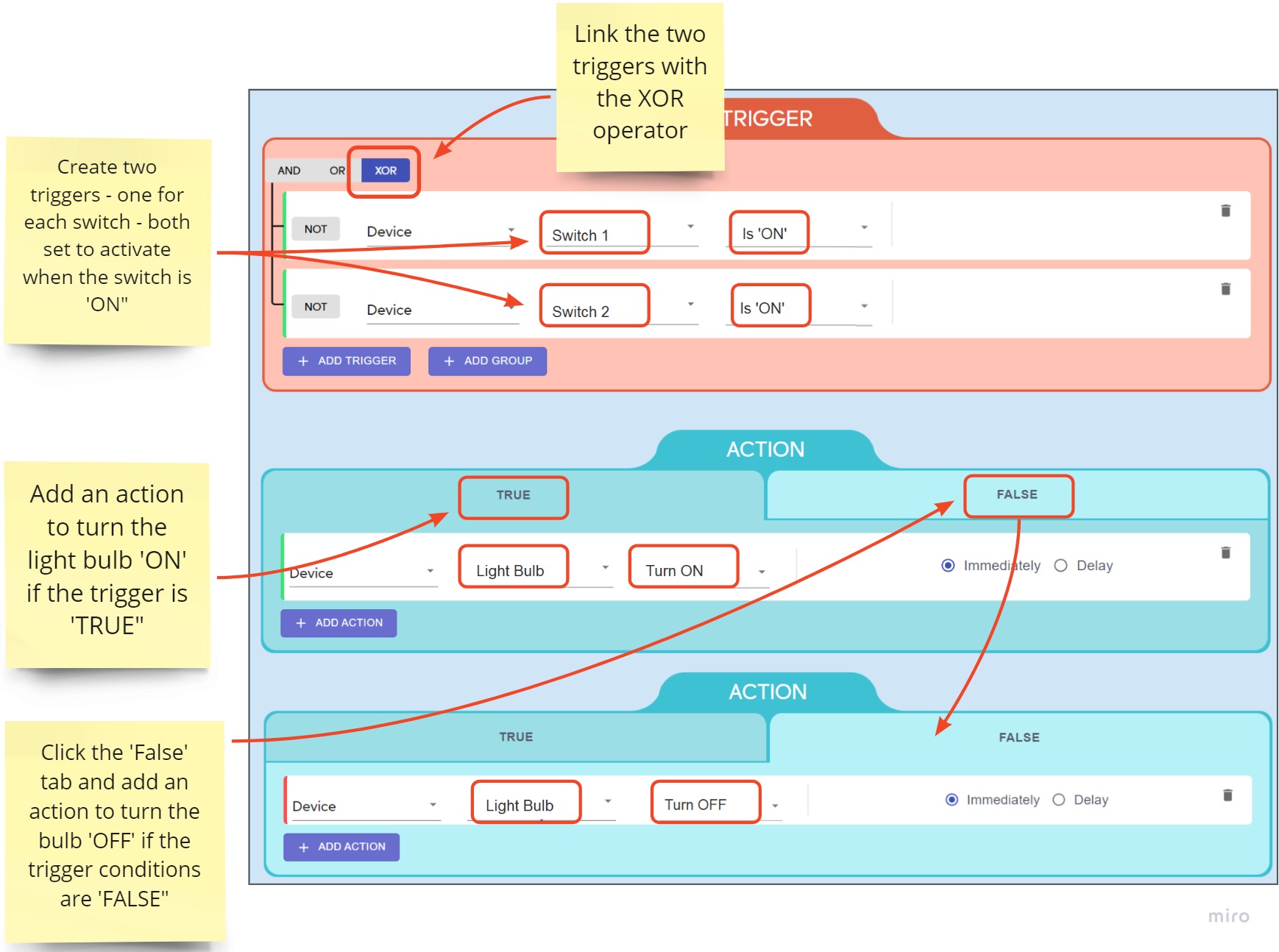
For a simple example, imagine a light bulb controlled by two physical switches whose on/off state is not exposed/apparent to users. Users simply flick one of the switches when they see the light is off but they want it on, and vice-versa.
So if only one switch is on, the light is turned on. But if the other switch is then also turned on, the light goes off. Then if either switch is flicked again (turned off), the light comes back on.
You could use XOR to create a meshbot that achieves this result as follows:
- Create a trigger that activates when switch 1 is ‘ON’
- Create another trigger that activates when switch 2 is ‘ON’
- Link the triggers with the XOR operator
- Set the ‘True’ action to turn the light bulb on
- Set the ‘False’ action to turn the light bulb off
Here’s a table explaining the bulb state in relation to the state of the two switches:
| Switch state | XOR’ed trigger state | ‘True’ action fired | ‘False’ action fired | Bulb State |
|---|---|---|---|---|
| Switch 1 — OFF | False | NO | YES | OFF |
| Switch 2 — OFF | ||||
| Switch 1 — OFF | True | YES | NO | ON |
| Switch 2 — ON | ||||
| Switch 1 — ON | True | YES | NO | ON |
| Switch 2 — OFF | ||||
| Switch 1 — ON | False | NO | YES | OFF |
| Switch 2 — ON |
XOR with 3 or more triggers
You can XOR more than two triggers together, but this requires we elaborate on the rules slightly:
- If there is an odd number of true conditions in your group, then the group is True.
- If there is a zero or even number of true conditions then the group is False.
| Trigger 1 | Trigger 2 | Trigger 3 | Trigger Group |
|---|---|---|---|
| False | False | False | False |
| False | False | True | True |
| False | True | False | True |
| False | True | True | False |
| True | False | False | True |
| True | False | True | False |
| True | True | False | False |
| True | True | True | True |
Why is this?
Because, strictly speaking, XOR gates only operate on two inputs at once (in our case, the inputs are trigger conditions). The system carries out an XOR calculation on the first two inputs then passes its result to the third input to form another pair. The true/false state of this latter pair determines the overall state of the trigger group.
Let’s use two rows from the table above as examples:
| Trigger 1 | Trigger 2 | Trigger 3 | Trigger Group |
|---|---|---|---|
| False | True | True | False |
Trigger 1 is ‘false’ and trigger 2 is ‘true’. When you apply the XOR requirement of ‘exactly one true condition’, this produces a derived ‘True’ output for the pair. This ‘true’ output is then placed alongside trigger 3 to form another pair and a second XOR calculation is performed on them. Trigger 3 has a state of ‘True’ and we know the state passed from the first pair is also ‘True’. That’s two ‘trues’, so this fails the XOR requirement of ‘exactly one true condition’ for the group and produces a ‘False’ result.
| Trigger 1 | Trigger 2 | Trigger 3 | Trigger Group |
|---|---|---|---|
| True | False | False | True |
Trigger 1 is ‘true’ and trigger 2 is ‘false’. Again, this first trigger pair produces a ‘true’ output after an XOR calculation because exactly one condition is true. This true output is placed alongside trigger 3, which in this case is ‘false’. An XOR calculation performed on the second pair produces a ‘True’ result because exactly one of the conditions is true.
You can try the same process for all the other rows in the table. You can also use any trigger pair as your ‘initial’ trigger pair. For example, you’ll get the same results if you XOR trigger 1 and trigger 3 first then compare it’s output to trigger 2.
This system scales as you increase the number of triggers but obeys the same ‘odd/even’ number of rules logic explained earlier.
NOT + AND
Will not execute the action if all conditions are true. Will run the action in all other circumstances.
NOT reverses the requirement of AND, so the group is true in situations where AND produces a false output. In other words, the group is only false when all linked conditions are true.
Here’s a table to illustrate how the states of 3 triggers linked by NOT + AND contribute to the state of the trigger group:
| Trigger 1 | Trigger 2 | Trigger 3 | Trigger Group |
|---|---|---|---|
| False | False | False | True |
| False | False | True | True |
| False | True | False | True |
| False | True | True | True |
| True | False | False | True |
| True | False | True | True |
| True | True | False | True |
| True | True | True | False |
NOT + OR
Will not execute the action if any or all conditions are true. Will only run the action if all linked triggers are false.
NOT reverses the requirement of OR, so the group is only true in situations where OR produces a false output.
Here’s a table to illustrate how the states of 3 triggers linked by NOT + OR contribute to the state of the trigger group:
| Trigger 1 | Trigger 2 | Trigger 3 | Trigger Group |
|---|---|---|---|
| False | False | False | True |
| False | False | True | False |
| False | True | False | False |
| False | True | True | False |
| True | False | False | False |
| True | False | True | False |
| True | True | False | False |
| True | True | True | False |
NOT + XOR
NOT reverses the requirement of XOR, so the group is true in situations where XOR produces a ‘false’ output.
Two-triggers under NOT + XOR
The group is true if > 1 or zero conditions are true. So if XOR wants ‘exactly one condition to be true’, then NOT + XOR wants ‘any situation except where exactly one condition is true’.
| Trigger 1 | Trigger 2 | Trigger Group |
|---|---|---|
| False | False | True |
| False | True | False |
| True | False | False |
| True | True | True |
Three or more triggers under NOT + XOR:
- If there is an odd number of true conditions in your group, then the group is False.
- If there is a zero or even number of true conditions in your group, then the group is True.
| Trigger 1 | Trigger 2 | Trigger 3 | Trigger Group |
|---|---|---|---|
| False | False | False | True |
| False | False | True | False |
| False | True | False | False |
| False | True | True | True |
| True | False | False | False |
| True | False | True | True |
| True | True | False | True |
| True | True | True | False |
Please read the explanation of how XOR gates work if you need more help with this.
NULL
The group does not contribute to the logic state of its parent group. However, logic elements within a NUL group still run and generate results, so subgroups of a NUL group can have activities.
DISABLE
Disabled groups are ignored, as if they don’t exist. Conditions in this group don’t run.